Jam and Replay Attacks on Vehicular Keyless Entry Systems
Bypassing Rolling Code Systems
Just to be clear, I worked on this project because I was interested in learning the basics of radio and how data is modulated...
Overview of Jam and Replay Attack
The attacker appropriates a device with simultaneous transmit and receive capabilities to produce a jamming signal, to restrict the car from receiving the validation code from the key fob. This is possible as Remote Keyless Entries are often intended with a receive band that is wider than the bandwidth of the key fob signal. The device simultaneously intercepts the rolling code by using a tighter receive band, and stores it for later use. When the user presses the key fob again, the device captures the second code and transmits the first code, so that the user’s required action is performed. This results in the attacker possessing the next valid rolling code, granting them access to the vehicle. The process can be repeated frequently by placing the device in the proximity of the car. Note that if the user unlocks the car using the mechanical key after the first try, the second code capture is not required, and the first code can be used to unlock the vehicle.
In this demonstrating I had used the HackRF to initially find the frequency that the key fob of Maruti Suzuki WagonR operates at and to analyze the signal and determine some of its properties. Then uses a Raspberry Pi running RPiTX to generate a jamming signal, and the HackRF to capture and replay the car keyfob signal.
Keyless Entry Systems
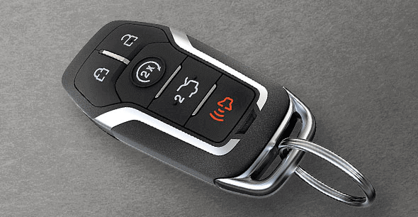
Figure 1: Key Fob
A remote keyless entry system simply refers to any electronic lock that functions without the use of a mechanical key. Commonly, this comes in the form of a key fob, with buttons that communicate using radio frequency (RF) signals with a receiver to perform a certain action, such as locking or unlocking a vehicle.
In this demonstration, The key fob was using a one-way RKE requires a manual button press to activate. The vehicle receives the signal and confirms that it is a valid code, then performs the required action. With a rolling code system, a cryptographically secure pseudorandom number generator (PRNG), installed in the vehicle and the key fob, is used to periodically change the required code after a keypress, usually with a buffer to account for accidental out-of-range button presses.
Quick Intro to RF Hardware & Software
Proof-of-Concept device
Several new technologies have made RF security testing simpler and more affordable for hobbyists and researchers, the most important development being the software-defined radio.
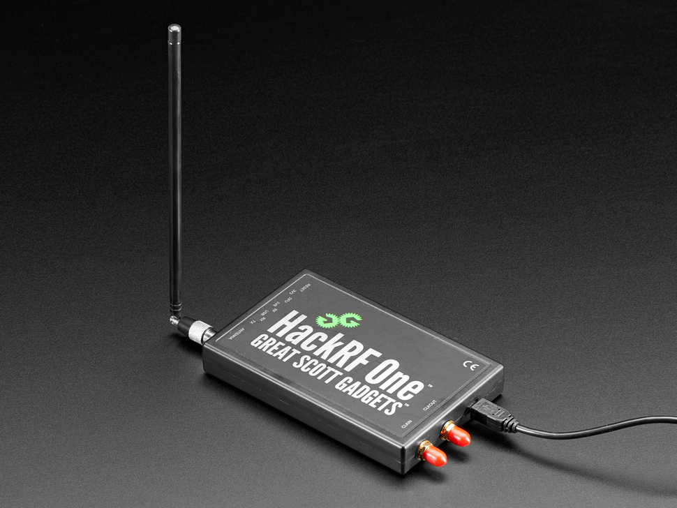
*Figure 2: HackRF used to analyze signal *
Software-Defined radio is a radio system where components traditionally implemented in hardware, such as filters and demodulators, are instead implemented in software. The setup typically involves an RF front end and an analog-to-digital converter, connected to a computer via USB. The computer performs complex tasks, such as demodulation, which refers to extracting the original signal from a carrier wave.
Besides, advances in computing hardware and software have allowed for complex signal analysis using graphical flow graph software, such as GNURadio, capable of manipulating, decoding and encoding data for use with software-defined radios. Another important development is the popular Raspberry Pi single-board computer, which offers a full Linux operating system running on a 900Mhz quad-core processor, 4 USB ports, display outputs and 40 general-purpose input-output (GPIO) pins, which provides an easy-to-use, affordable testing base for the experimental jam and replay attack outlined below.
Initial Reconnaissance
The first step in reverse engineering the key fob was to determine its operating frequency. Hence, the HackRF was utilized. The method for finding the operating frequency is to repeatedly press the key fob until a signal became visible on the fast Fourier transform (FFT) plot, which displays a live view of the RF spectrum. The horizontal axis represents frequency in megahertz and the vertical axis the amplitude in decibels relative to full scale (dBFS). A waterfall plot is shown in the bottom half, which plots the FFT over time, with the colors representing signal amplitude (blue to red, in increasing signal strength).
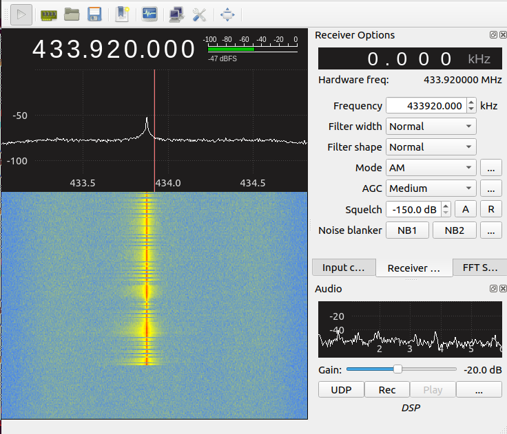
*Figure 3: FFT plot of frequency versus signal strength showing key fob signal at 433.92MHz *
As seen in Figure 3, there is a peak at 433.878MHz, with the entire signal centered at 433.92MHz. However, the FFT plot does not provide information regarding how the data is encoded.
Receiving The Signal
For this attack, I used a HackRF for receiving any data. I used a GNURadio flow graph with the HackRF to receive and decode the keyfob data.
This the GNURadio flow graph: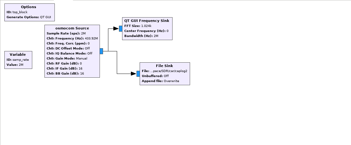
*Figure 4: GNURadio flow graph for capturing the signal *
Things to note in the flow graph:
- Set the sample rate to 2M which is the lowest sample rate recommended when using HackRF
- osmocom source block
- Frequency –> 433.92MHz
- RF gain –> 0
- IF gain –> 16
The output is simply raw data, that is then processed by xxd to obtain hex values for every piece of the data.
1 | xxd "saved_file" | less |
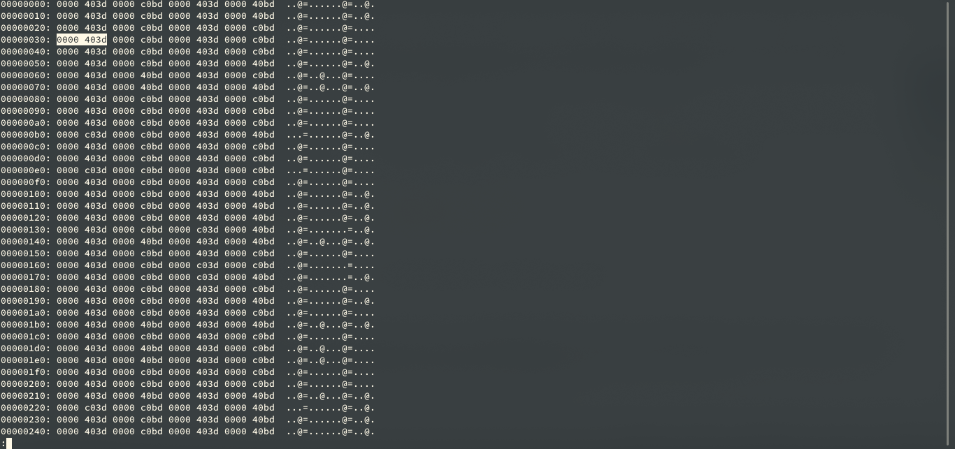
Figure 5: Hex dump
The hex dump will be printing out lots of redundant information in his file. The reason behind the pattern which we see 4 bytes long is because what we are saving is the complex data type and that is a pair of floats. So what we are seeing is here is one floating-point for i and q (Complex Number). It is a 64-bit sample for one quadrature sample. There is a limited number of values we because these have been converted from 8 bit signed integer to 32-bit floats.
If we use a different tool like od tool with floating-point enabled it will dump out the floating-point.
- w8 is used for interpreting 8 bits at a time
1 | od -f -w8 "saved_file" | less |
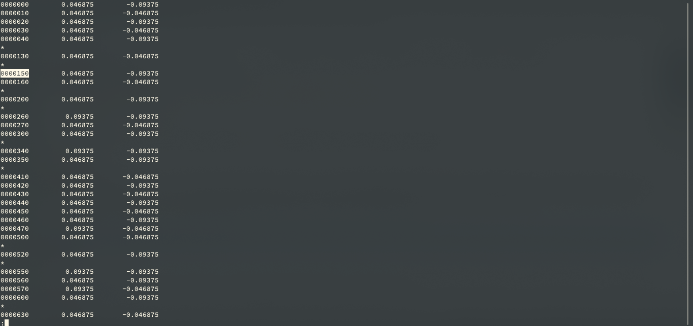
Figure 6
Automated Decoding
To further analyze the signal, a Debian setup was utilized, and the gqrx SDR receiver software used to record the key fob I/Q data. The data was passed to inspectrum, an open-source waveform analysis tool. A screenshot of the beginning of the signal is shown in Figure 6.
1 | inspectrum -r 2e6 "saved_file" |
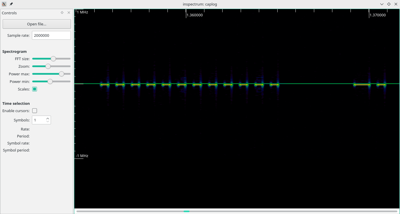
Figure 7
Analyzing through the spectrum it is clear that the signal is using ON/OFF Keying. The key fob is using a rolling code signal, which is repeated twice, divided by a gap, seen in Figure 7. At first guess, the signal appears to be Manchester encoded, which means every bit (zero or one) is either encoded as high then low or low then high, for the same period.
How Rolling Code Work
Most car manufacturers nowadays practice a keyless entry system called rolling codes. This was put into place to counter replay attacks, in which the attacker captures the unlock signal produced by the keyfob, and replays it to the car later.
The way this was done was by making the devices have a synchronized starting code that was sent and an algorithm that determined the following code to be sent next so that the same code was never repeated.
The implementation of this is that both the car and the remote are synced to an initial number (A PRNG’d seed). This is usually called “pairing” a remote and relies on some configuration of the device such as pressing a button or using a ‘master’ key.
Once the remote and device are synchronized they use an algorithm to take that initial number (x) and then transform it to the next number in the sequence (x+1). The subsequent keypress will take the result of the prior keypress as the input.
The devices store the next code that needs to be transmitted to validate it and also store a “list” of them (approximately 255). This “list” is created to prevent the devices to not go out of sync, even if the user accidentally pressed it inside your house before walking over to your car.
To keep sync as soon as a valid button keypress is received, the “list” is updated to be x iterations from that keypress.
This also implies that all rolling code systems will suffer from a denial of service situation where if the button is pressed too many times without it being received from the device the buttons lose sync and will stop working.
How do we attack rolling codes?
Rolling code systems are vulnerable to several attacks that have been presented over the years. A number of these are attacks on the hardware itself through things like power analysis to determine the seed number or maths algorithm used. One example is the side channel attacks
I will only look at the basic attacks that are against the radio transmissions rather than the hardware. This makes these a lot easier to implement as the hardware and software requirements are a lot lower.
Executing The Attack
Jam and Replay Hardware
To simplify the system, a HackRF transceiver was used, that is capable of receiving and transmitting in various industrial, scientific and medical (ISM) unlicensed bands, including 433MHz, with wide support for modulations such as FSK, ASK (amplitude-shift keying) and OOK (on-off keying). Further settings such as the modem modulation, frequency deviation, data rate (calculated using inspectrum), channel bandwidth, and packet sync mode were configured to match the key fob’s characteristics.
Jamming Signal
To create the jamming signal, the open-source rpitx software was utilized, which is capable of transmitting RF signals via the Raspberry Pi’s GPIO pins. Specifically, the variable-frequency oscillator (VFO) mode was used, as it offers “precise frequency resolution”. A carrier signal was transmitted at 433.850MHz, slightly below the operating frequency of the key fob, however within the automobile’s receive bandwidth.
1 | sudo ./rpitx –m VFO –f 433850 |
Replaying Signal
First, we could try sending the captured signal to osmocom sink (take input from the source file and deliver it to HackRF for transmitting.)
This the GNURadio flow graph: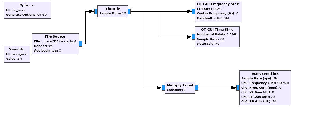
*Figure 8: GNURadio flow graph for replaying the signal *
we use a throttle block since we don't want to crush the CPU.
Things to note in the flow graph:
- frequency –> 433.92e6 for transmitting.
- RF gain –> 0
- IF gain –> 20 (IF gain affect the transmitter, 20 is roughly in the midpoint of maximum IF gain )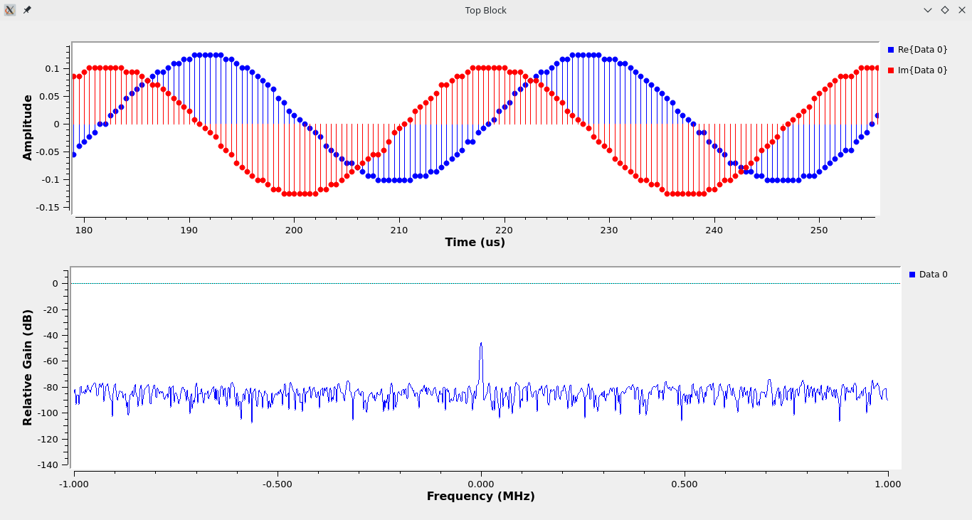
Figure 9: Time Sink
- We should increase the power of transmission by amplifying the digital domain before converting it into the analog domain. As we can see in Figure 9 that the amplitude of the transmitting signal is fairly low compared to the captured signal.
Heres a GIF of me testing the code for the first time.
I had included the this repo which contain the files related to this project